Bending Guidelines
Use these guidelines to design sheet metal parts that quote cleanly and bend without surprises. The checks that matter most are bend angle, material thickness, flange length, reverse bend clearance, and feature placement near bends.
File Checklist
Before you upload a bent sheet metal part, run through this list:
- Export the part as a 3D STEP file
- Confirm the material and thickness are in our bending range
- Confirm each bend angle is within our capability range
- Check minimum flange lengths
- Check reverse bends, return flanges, channels, joggles, and box shapes for punch clearance
- Keep critical features outside the distortion zone
If you have questions about our process, use the chat bubble or email support@fabworks.com.
Bending Capabilities
Our press brake bends most common sheet metal materials up to 0.250" thick. Parts that follow these guidelines get the fastest lead times and the cleanest results. If a part falls outside them, our quoting engine flags it before you order.
Material Range
- Thicknesses: 0.030" to 0.250"
- Materials: Aluminum 5052-H32, Steel 1008, Steel A36, Stainless Steel 304-2B, Galvanized Steel G90
- Maximum bend length: see the material table below
For thickness and bend length combinations by material, see the materials pages.
Bend Angle
The maximum bend angle depends on the material, thickness, and tooling used for the part. Use the material table at the bottom of this page to confirm the limit for the stock you plan to use.
If your part has a return flange, channel, joggle, or box shape, also check the reverse bend clearance section below. Tooling clearance can limit a part even when the bend angle itself is within range.
Minimum Flange Lengths
The minimum flange length is the shortest straight run of material allowed between a bend and the edge of the sheet. Anything shorter can slip into the V-die or buckle during bending, which ruins the part.
The minimum depends on the V-die and the bend angle. Material and thickness can change which V-die we use, but for the same die and angle, thickness alone does not change the minimum. The calculator below estimates the value for your part.
How to Measure Flange Length
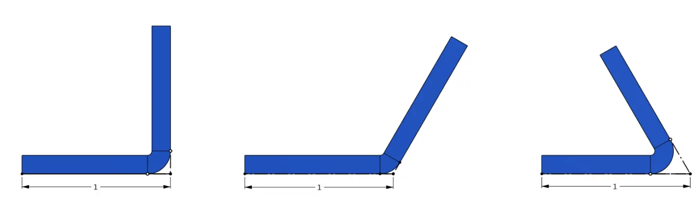
Measure flange length to the apex of the bend, not along the finished flat face. At the same flange length, a sharper bend leaves less flat surface.
Flange Length Calculator
Select the material, thickness, and bend angle. The green dimension is the minimum flange length. The orange dimension and hatched area mark the approximate distortion zone.
Minimum flange calculator
See where the short flange must reach to stay supported during bending.
Minimum flange 0.500 in · 12.69 mm. Distortion zone 0.375 in · 9.52 mm.
Want us to check the whole part? Upload your STEP file. Our software checks every flange against the minimum length and flags critical features inside the distortion zone.
Minimum Joggle Spacing
A joggle uses two close, opposite bends to offset one face of the sheet from the other. As the second bend forms, the first bend has to clear the lower die through the full stroke. If the bend lines sit too close together, the sheet hits the side of the die before the joggle is finished. Specialized joggle tooling can make tighter offsets, but we form every joggle with our standard press brake tooling.
Select a material and thickness, then use the 1 × t or 2 × t shortcuts for common joggle offsets. The calculator shows the bend angle needed to reach that offset while still meeting our minimum flange length.
Minimum joggle calculator
Find the tightest joggle for your material, thickness, and finished angle.
Finished angle 167.83°. Surface offset 0.125 in.
Reverse Bends
A reverse bend is any bend where the punch has to reach into a channel formed by an earlier bend. Z-bends, joggles, U-channels, return flanges, and boxes all qualify. For these features, punch clearance sets the limit.
Reverse Bend Clearance Checker
Use the checker below when your part has a return flange or box feature. The colored curves show the clearance envelopes for the punch styles our quoting engine can select.
Reverse Bend Clearance Checker
Compare return flanges and box bends against available press-brake punch clearance.
Values show punch, upper-tool extension, and machine-frame contact thresholds for the selected angles with both extensions installed. Leave about 0.05" below the curve for a conservative production margin.
Box Depth Clearance Calculator
A four-sided box also has to clear the machine while its last two sides are formed. Select the material and thickness, then enter the finished outside length, width, and depth. The calculator checks both bend orders, with the length sides or the width sides formed last. It shows whether the sides formed first will clear.
Box Depth Clearance Checker (Beta)
Compare the last two bends of a four-sided box against available press-brake clearance.
Length sides last. The box clears during bending.
Width sides last. The box clears during bending.
Bend Radius
We air bend, so the finished radius of a bend does not exactly match the punch radius. The sheet forms across the die opening and springs back slightly, which means the finished inside and outside radii depend on material and thickness as well as tooling.
Select the material, thickness, and finished angle to see the approximate finished inside (ID) and outside (OD) radius for your part.
Bend radius calculator
Estimate the finished inside and outside radius for your material, thickness, and bend angle.
Cross-section of a bend in 0.125 in Aluminum 5052-H32. The green line is the inside radius: 0.076 in, or 1.92 mm. The purple line is the outside radius: 0.201 in, or 5.09 mm. The amber line is the punch radius: 0.039 in, or 1.00 mm.
Tolerances
- Single bends are held to a +/- 0.015" length tolerance
- Single bends are held to a +/- 1 degree angle tolerance
- Features separated by multiple bends have an additional +/- 0.015" tolerance for each separating bend
- Die marks will be visible on all bends
K-Factor
The K-factor sets where the neutral axis sits inside a bend, which determines how much material each bend consumes when the part is unfolded into a flat pattern.
You do not need to calibrate a K-factor for us. Upload the finished 3D STEP model and we generate the flat pattern from that geometry, using the bend radius and K-factor for our own tooling and process. Model the part to its finished bent dimensions. Your CAD K-factor only affects flat patterns you generate yourself and does not need to match ours.
What We Can't Bend
- Bends longer than the maximum length listed for that material in the table below
- Bends past the maximum angle listed for that material and thickness
- Reverse bends that exceed the available punch clearance envelope
- Materials not in our standard inventory
Not sure if your part is bendable? Upload your STEP file and our software checks it in seconds.
Material Table
This table lists stock thickness, nominal tooling radius, estimated finished inside radius at 90° and 135° included angles, minimum flange length, maximum bend length, and maximum bend angle for each material. The finished radius values are approximate. Production geometry and bend deductions still use the nominal tooling radius.
| Material | Thickness | Max Bend Length | Max Angle | Min Flange Length 90° | Distortion Zone 90° | Est. Radius 90° |
|---|---|---|---|---|---|---|
| Aluminum 5052-H32 | 0.032" | 96" | 135° | 0.268" | 0.201" | 0.055" |
| Aluminum 5052-H32 | 0.040" | 96" | 135° | 0.268" | 0.201" | 0.054" |
| Aluminum 5052-H32 | 0.050" | 96" | 135° | 0.268" | 0.201" | 0.053" |
| Aluminum 5052-H32 | 0.063" | 96" | 135° | 0.268" | 0.201" | 0.051" |
| Aluminum 5052-H32 | 0.080" | 96" | 135° | 0.268" | 0.201" | 0.049" |
| Aluminum 5052-H32 | 0.090" | 96" | 135° | 0.380" | 0.285" | 0.063" |
| Aluminum 5052-H32 | 0.100" | 96" | 135° | 0.380" | 0.285" | 0.061" |
| Aluminum 5052-H32 | 0.125" | 96" | 135° | 0.500" | 0.375" | 0.076" |
| Aluminum 5052-H32 | 0.160" | 62.75" | 90° | 0.592" | 0.444" | 0.177" |
| Aluminum 5052-H32 | 0.187" | 62.75" | 90° | 0.708" | 0.531" | 0.185" |
| Aluminum 5052-H32 | 0.250" | 54.5" | 90° | 0.883" | 0.662" | 0.197" |
| Galvanized Steel G90 | 0.024" | 96" | 135° | 0.268" | 0.201" | 0.060" |
| Galvanized Steel G90 | 0.036" | 96" | 135° | 0.268" | 0.201" | 0.058" |
| Galvanized Steel G90 | 0.048" | 96" | 135° | 0.268" | 0.201" | 0.056" |
| Galvanized Steel G90 | 0.059" | 96" | 135° | 0.268" | 0.201" | 0.055" |
| Galvanized Steel G90 | 0.074" | 96" | 135° | 0.268" | 0.201" | 0.052" |
| Stainless Steel 304-2B | 0.030" | 96" | 135° | 0.268" | 0.201" | 0.092" |
| Stainless Steel 304-2B | 0.048" | 96" | 135° | 0.268" | 0.201" | 0.085" |
| Stainless Steel 304-2B | 0.060" | 96" | 135° | 0.268" | 0.201" | 0.080" |
| Stainless Steel 304-2B | 0.074" | 96" | 135° | 0.380" | 0.285" | 0.119" |
| Stainless Steel 304-2B | 0.100" | 96" | 135° | 0.500" | 0.375" | 0.154" |
| Stainless Steel 304-2B | 0.120" | 73.5" | 90° | 0.592" | 0.444" | 0.192" |
| Stainless Steel 304-2B | 0.187" | 46.5" | 90° | 0.883" | 0.662" | 0.320" |
| Stainless Steel 304-2B | 0.250" | 28.5" | 90° | 1.161" | 0.871" | 0.403" |
| Steel 1008 | 0.024" | 96" | 135° | 0.268" | 0.201" | 0.060" |
| Steel 1008 | 0.036" | 96" | 135° | 0.268" | 0.201" | 0.058" |
| Steel 1008 | 0.048" | 96" | 135° | 0.268" | 0.201" | 0.056" |
| Steel 1008 | 0.059" | 96" | 135° | 0.268" | 0.201" | 0.055" |
| Steel 1008 | 0.074" | 96" | 135° | 0.268" | 0.201" | 0.052" |
| Steel 1008 | 0.104" | 96" | 135° | 0.500" | 0.375" | 0.088" |
| Steel 1008 | 0.119" | 96" | 135° | 0.500" | 0.375" | 0.085" |
| Steel 1008 | 0.135" | 77" | 90° | 0.592" | 0.444" | 0.105" |
| Steel 1008 | 0.187" | 62.75" | 90° | 0.883" | 0.662" | 0.217" |
| Steel A36 | 0.250" | 28.5" | 90° | 1.161" | 0.871" | 0.254" |
Tube
Tolerances, stock sizes, features, and other guidelines that are important to know when designing parts for our tube laser cutting service.
Hardware
Hardware insertion is the process of installing PEM nuts, studs, standoffs, and other fasteners into sheet metal parts. These components are essential for the assembly of sheet metal parts and are often used to attach other components like PCBs, panels, and other sheet metal parts.